TODO introduction
CASTOR V19 definitions
The axial profile for a CASTOR V19 is describe in the following table:

The CASTOR stands vertically. The table gives coordinates of vertical planes (pz).
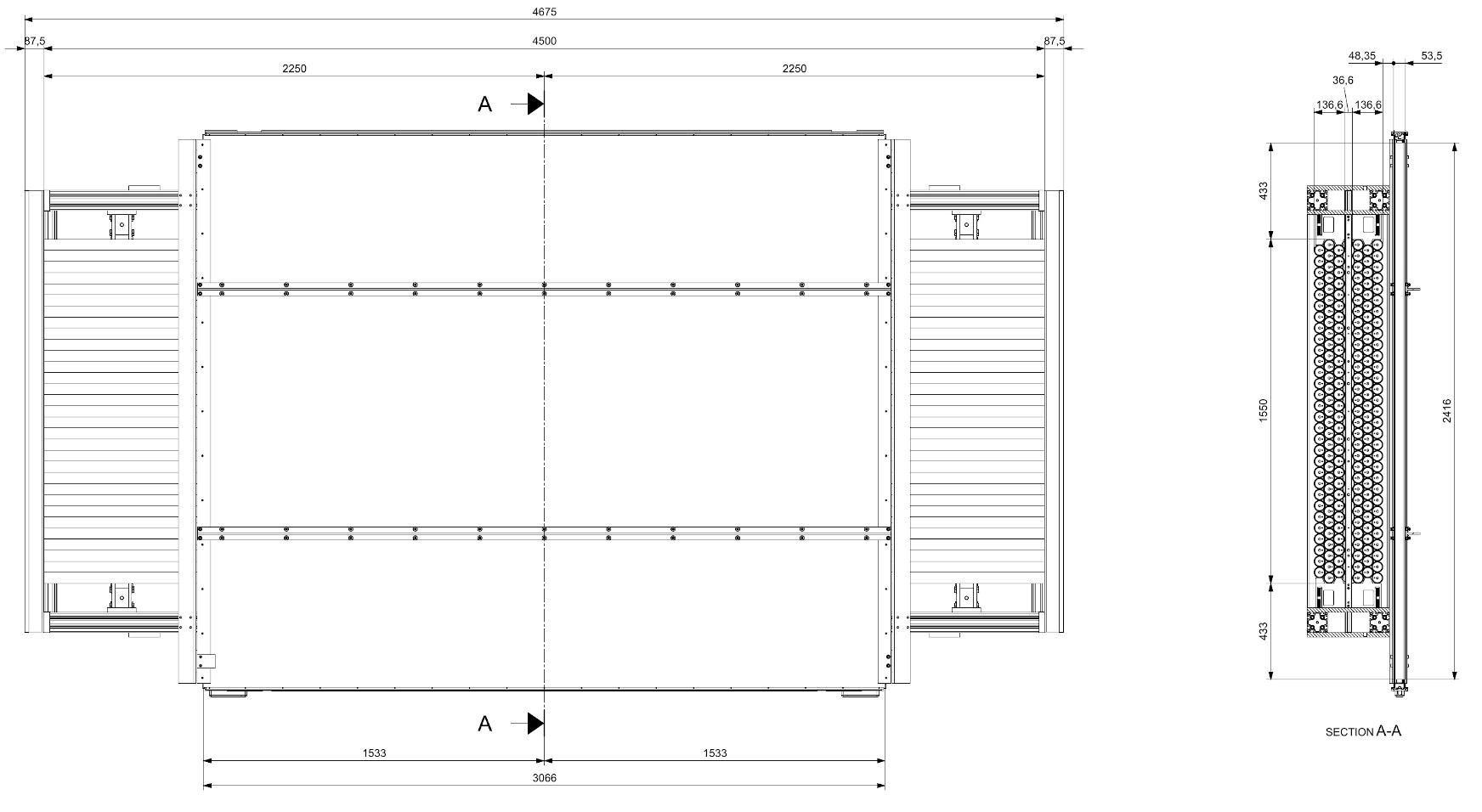
The outline of the CASTOR is the following:

The densities and materials of complex-to-model structures, like plenum and foot/top of fuel assemblies have been obtained by smearing all materials. The same approach is used when modelling the active part of spent fuel. The assembly starts from the bottom foot that is from -59.9 to -33.7, that is at 40.1 to 66.3 cm from the bottom of the cask and ends at 433.65, that is 533.65 cm from the bottom of the cask. The real assembly consists from 5 different zones (from top to bottom):
- Top of FA (hanging mechanism)
- Top plenum of FA
- Active part – spent fuel
- Bottom plenum of FA
- Foot of FA
The standard numbering of the fuel assemblies inside the cask is the following:

The old numbering of the fuel assemblies inside the cask is:

The detector
The following schema describes one of the two parts of the detector: