Author(s)
| Name | Institution | Mail Address | |
|---|---|---|---|
| Luca Rei | INFN Sezione diGenova | luca.rei@ligo.org |
How to Obtain Support
| luca.rei@ligo.org |
General Information
| ML/DL Technologies | LSTM |
|---|---|
| Science Fields | General Relativity |
| Difficulty | Low |
| Language | English |
| Type | fully annotated / runnable / external resource / ... |
Software and Tools
| Programming Language | Python |
|---|---|
| ML Toolset | Keras + Tensorflow |
| Suggested Environments | bare Linux Node |
Needed datasets
| Data Creator | Virgo/Ligo |
|---|---|
| Data Type | real acquisition |
| Data Size | 1 GB |
| Data Source | IGWN collaboration |
Short Description of the Use Case
Gravitational waves (gw) are 'ripples' in space-time caused by some of the most violent and energetic processes in the Universe. Albert Einstein predicted the existence of gravitational waves in 1916 in his general theory of relativity. Einstein's mathematics showed that massive accelerating objects (such as neutron stars or black holes orbiting each other) would disrupt space-time in such a way that 'waves' of undulating space-time would propagate in all directions away from the source. These cosmic ripples would travel at the speed of light, carrying with them information about their origins, as well as clues to the nature of gravity itself.
While the processes that generate gravitational waves can be extremely violent and destructive, by the time the waves reach Earth they are thousands of billions of times smaller! In fact the amount of space-time wobbling they generated is of the magnitude of a 1000 times smaller than the nucleus of an atom!
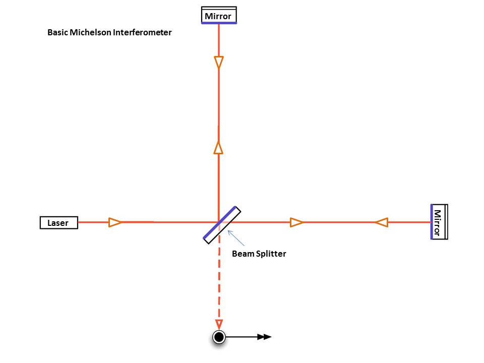
A sensitive class of detector uses a laser Michelson interferometer to measure gravitational-wave induced motion between separated 'free' masses.
Interferometers are investigative tools used in many fields of science and engineering. They are called interferometers because they work by merging two or more sources of light to create an interference pattern, which can be measured and analyzed; hence 'Interfere-o-meter', or interferometer. The interference patterns generated by interferometers contain information about the object or phenomenon being studied. They are often used to make very small measurements that are not achievable any other way. This is why they are so powerful for detecting gravitational waves--LIGO's interferometers are designed to measure a distance 1/10,000th the width of a proton.
The basic configuration of a Michelson laser interferometer is shown in fig below. It consists of a laser, a beam splitter, a series of mirrors, and a photodetector (the black dot) that records the interference pattern.
The principles of interference are simple to understand. Two or more waves interact. You add the heights of the separate waves together as they interact, and the resulting wave is the 'interference' pattern. The figure at right shows two specific kinds of interference: total constructive interference and total destructive interference. Total constructive interference happens when the peaks and troughs of two (or more) waves perfectly meet up. When added together, you 'construct' a larger wave, the size of which is equal to the sum of the heights (and depths!) of the two waves at each point where they are physically interacting. Total destructive interference occurs when the peaks of one or more waves meet and match the troughs of an identical wave. Adding these together results in them cancelling each other out (i.e., they 'destroy' each other).
In nature, the peaks and troughs of one wave will not always perfectly meet the peaks or troughs of another wave like the illustration shows. Conveniently, regardless of how in-sync they are when they merge, the height of the wave resulting from the interference always equals the sum of the heights of the merging waves along each point where they are physically interacting. So when waves meet a little out of sync, partial constructive or destructive interference can occur. The animation below illustrates this effect. The black wave shows the result of adding together the peaks and troughs of the red and blue waves as they move through (interfere with) each other. Adding up the heights/depths of each wave at each point as they move through each other results in the black wave. Note that it experiences a full range of heights from twice as high/deep (total constructive interference) to flat (total destructive interference). In this example, the black wave is the interference pattern (the pattern that results from the continuing interference fo the red and blue wave). Note how it continues to change as long as the red and blue waves continue to interact.
Gravitational waves cause space itself to stretch in one direction and simultaneously compress in a perpendicular direction. This causes one arm of the interferometer to get longer while the other gets shorter, then vice versa, back and forth as long as the wave is passing. The technical term for this motion is "Differential Arm" motion, or differential displacement, since the arms are simultaneously changing lengths in opposing ways, or differentially.
As described above, as the lengths of the arms change, so too does the distance traveled by each laser beam. A beam in a shorter arm will return to the beam splitter before the beam in a longer arm, then the situation switches as the arms oscillate between being longer and shorter. Arriving at different times, the waves of light no longer meet up nicely when recombined at the beam splitter. Instead, they shift in and out of alignment or "phase" as they merge while the wave is causing the arm lengths to oscillate. In simple terms, this results in a flicker of light emerging from the interferometer.
Interferometers act as a pass band on the signal, having a different rensponse to different frequencies, for this reason signal need to be corrected (with frequencies dependent weight), we call it "whitening" step.
Once whitened it is time to search for signal, we generally apply a matched filter between the signal and a "template" (a simulated event).
In this tutorial, we will follow another approach, instead of simulated an event and searching for it inside a signal we will answer a different question: does this acquisition contains different information compared to a signal with a gw inside it? We will usie a machine learning algorithm.
This is in fact a simple example on how use an autoenconder to efficient data codings and foldings
"An autoencoder is a type of artificial neural network used to learn efficient data codings in an unsupervised manner. The aim of an autoencoder is to learn a representation (encoding) for a set of data, typically for dimensionality reduction, by training the network to ignore signal “noise”."
In the following we will use the autoencoder to analyse a gravitation wave format file and learn how to ignore some sources of noise, obtain a signal cleaned and a size reductioned
All data files used for this exercise are public and can be obtained from the Ligo website at https://www.gw-openscience.org/archive/O2_16KHZ_R1/ in the gwf format or hdf5 format
At https://www.gw-openscience.org/ you could find many interesting tutorial on how read plot and analyze with standard technique the gravitational files
How to execute it
Download data files (any files at https://www.gw-openscience.org/data/ will be good) and execute the Jupyter notebook (https://github.com/luca-rei/ml-genoa). For convenience in the Jupyter we assume to work with hdf5 files,the interesting part is how the output of an encoded signal (gw) differ from an encoded noise (compare their size and their entropy). For example try to encode different data...
Annotated Description
References
https://blog.keras.io/building-autoencoders-in-keras.html